Parker Hannifin VIX500IM Manuel d'utilisateur
Naviguer en ligne ou télécharger Manuel d'utilisateur pour Non Parker Hannifin VIX500IM. Parker Hannifin VIX500IM User's Manual Manuel d'utilisatio
- Page / 218
- Table des matières
- DEPANNAGE
- MARQUE LIVRES
- V iX250IM 1
- V iX500IM 1
- Stepper Drives 1
- User Guide 1
- SAFETY WARNING 3
- Contact Addresses 5
- Contents 6
- Latest Changes Sheet 7
- 1. Introduction 8
- Product Variants 9
- Product Features 9
- 1. INTRODUCTION 3 10
- Fit Kits 10
- Further Information 11
- 2. Mechanical Installation 12
- Drive Dimensions 13
- 2. MECHANICAL INSTALLATION 7 14
- Drive Mounting Options 14
- 3. Electrical Installation 16
- Power Supply Connections 17
- Power Supply Options 18
- XL-PSU Power Supply 20
- EARTH (GND.) 21
- PL1100 Power Supply 23
- General Description 23
- EMC Installation 24
- General Requirements 24
- +24V Supply Connections 24
- Motor Cables 27
- Motor Phase Contactors 27
- Motor Selection 28
- MOTOR CONNECTOR 29
- PARALLEL 29
- CONNECTIONS 29
- Custom Motor Set Up 30
- Short Circuit Protection 33
- Terminal Description 35
- X2 Connector 36
- X3 Connector 37
- Inter-drive RS232 Connections 38
- X4 Connector 39
- X5 Connector 42
- User Inputs 43
- Positive limit input 46
- Negative limit input 46
- CAN Bus Termination 48
- 4. Control of ViX Drives 52
- 4. CONTROL OF VIX DRIVES 47 54
- 4. CONTROL OF VIX DRIVES 49 56
- LOOP Command 56
- Fault Label 57
- 4. CONTROL OF VIX DRIVES 51 58
- 4. CONTROL OF VIX DRIVES 53 60
- Start Label 60
- Use of the LSEL Command 61
- 4. CONTROL OF VIX DRIVES 55 62
- Table of System Variables 63
- 4. CONTROL OF VIX DRIVES 57 64
- 4. CONTROL OF VIX DRIVES 59 66
- (revs/sec) 68
- 4. CONTROL OF VIX DRIVES 63 70
- Trapezoidal S-Curve 71
- 1458 32Bit No 72
- 4. CONTROL OF VIX DRIVES 69 76
- 4. CONTROL OF VIX DRIVES 71 78
- Conditional Code 79
- Conditional Code Example 80
- Move Types 81
- Motion Profiles 82
- Trapezoidal Profile 83
- Registration 83
- 4. CONTROL OF VIX DRIVES 77 84
- 4. CONTROL OF VIX DRIVES 79 86
- Homing Configuration Command 87
- 4. CONTROL OF VIX DRIVES 81 88
- HFrps HFrps 89
- 4. CONTROL OF VIX DRIVES 83 90
- 4. CONTROL OF VIX DRIVES 85 92
- Following and Limits 92
- Using Closed Loop Operation 94
- Position Maintenance 95
- 4. CONTROL OF VIX DRIVES 89 96
- Stall Detection 98
- 4. CONTROL OF VIX DRIVES 93 100
- 5. Easi-V Software 102
- Installation Procedure 103
- 5. EASI-V SOFTWARE 97 104
- Uninstalling Easi-V 104
- Software Operation 104
- 5. EASI-V SOFTWARE 99 106
- Menu Overview 106
- 5. EASI-V SOFTWARE 101 108
- Terminal Menu Selections 109
- Communicating with a Drive 109
- 5. EASI-V SOFTWARE 103 110
- Configure Terminal Buttons 110
- Utilities Menu Selections 111
- 5. EASI-V SOFTWARE 105 112
- 5. EASI-V SOFTWARE 107 114
- 5. EASI-V SOFTWARE 109 116
- Drive settings / Setup 117
- 5. EASI-V SOFTWARE 111 118
- 5. EASI-V SOFTWARE 113 120
- Confirming Drive Operation 121
- 6. Command Reference 122
- Attention 123
- Command Properties 123
- 6. COMMAND REFERENCE 117 124
- Acceleration/Deceleration 126
- Acceleration 126
- Deceleration 127
- Enable label triggered code 128
- Continue 130
- Clear user code 130
- Distance 131
- 6. COMMAND REFERENCE 125 132
- Enable/Disable Communications 133
- Exit from loop 134
- Configure following 135
- 6. COMMAND REFERENCE 129 136
- Feed Rate Override 137
- 6. COMMAND REFERENCE 131 138
- GO to SUBroutine 139
- 6. COMMAND REFERENCE 133 140
- GO TO routine 141
- Change direction 142
- Configure Homing 144
- 3HOME1(-,1,-15,100,1) 145
- Test condition 146
- Input Status 147
- 6. COMMAND REFERENCE 141 148
- Configure limit inputs 149
- List user program 150
- LoadEnc settings 151
- Repeat user code 152
- Label Select 153
- 6. COMMAND REFERENCE 147 154
- 6. COMMAND REFERENCE 149 156
- Motor Settings 158
- Shutdown motor power 160
- Turn ON motor power 161
- Position maintenance 162
- Define move profile 164
- Report system parameter 166
- Registration move 167
- 6. COMMAND REFERENCE 161 168
- Return to factory settings 169
- 6. COMMAND REFERENCE 163 170
- Scale settings 171
- 6. COMMAND REFERENCE 165 172
- Stall detect 173
- 6. COMMAND REFERENCE 167 174
- STATUS of Drive 175
- STOP Input 176
- Save configuration 177
- Time delay 178
- Wait for trigger 179
- Velocity 180
- Write system variable 181
- Set comms address remotely 182
- Quote command 183
- 6. COMMAND REFERENCE 177 184
- System Variables 184
- 6. COMMAND REFERENCE 179 186
- Drive Faults 187
- 6. COMMAND REFERENCE 181 188
- Status Bits 188
- User Faults 189
- 6. COMMAND REFERENCE 183 190
- Command List 190
- Maintenance 192
- Troubleshooting 192
- Communication Problems 193
- Drive LED Indicators 194
- Complete LED Diagnostics 195
- Forcing a Hardware RFS 196
- Returning the System 201
- 8. Hardware Reference 202
- Indexer Specification 203
- 8. HARDWARE REFERENCE 204
- Appendix A 206
- 1.5 X secondary VA 207
- Appendix B 208
- APPENDIX B 209
- Customer Feedback 216
- Feedback, Digital encoder 218
- Energise/Shutdown* 218
Résumé du contenu
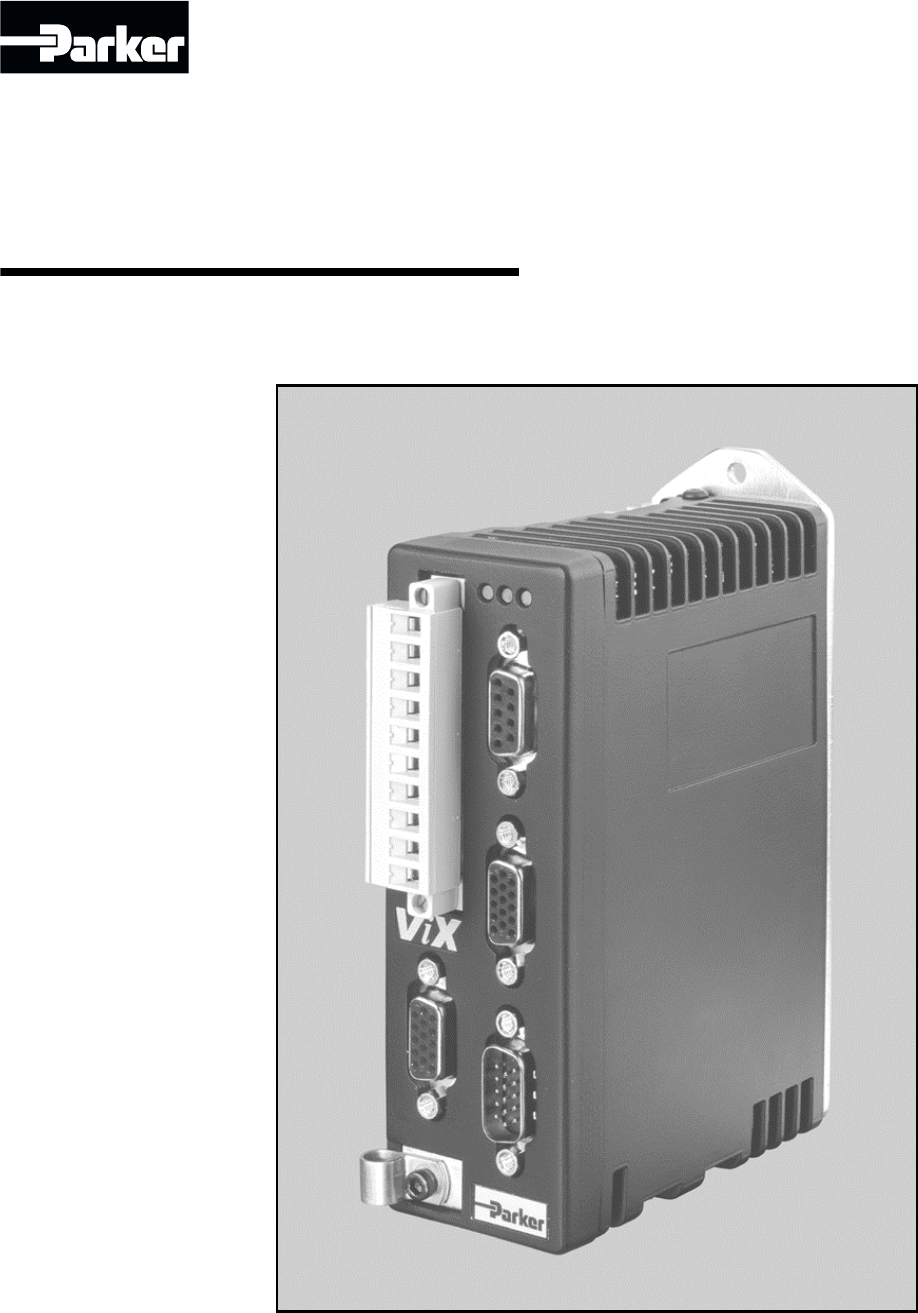
Part No: 1600.324.01b February, 2004 (For software revision 2.0 onwards)V iX250IMV iX500IMStepper DrivesUser Guide
1. INTRODUCTION 3Fit KitsA fit kit is available for ViXIM drives:VIX-KITPart Number Quantity Description1650.937.01 1 Informationsheet5004.023 1 Plas
4. CONTROL OF VIX DRIVES 93You can use SCALE in combination with other commands such as LOADENC, STALL orPOSMAIN. The exact mix of commands together
VIX IM MICROSTEPPER INDEXER DRIVE USER GUIDE94
5. EASI-V SOFTWARE 955. Easi-V SoftwareComputer RequirementsTo be able to run Easi-V software, necessary for the control and programming of the ViX,
VIX IM MICROSTEPPER INDEXER DRIVE USER GUIDE96Installation ProcedureThis procedure takes you quickly through the steps necessary to install Easi-V on
5. EASI-V SOFTWARE 976. Once you have selected a destination for Easi-V or have decided to use thedefault directory, select NEXT to begin file trans
VIX IM MICROSTEPPER INDEXER DRIVE USER GUIDE98Figure 5-3. Easi-V Product SelectionSelecting Product from the Utilities menu will also display the pro
5. EASI-V SOFTWARE 99Menu OverviewFileFiling OperationsCreates a new editor file, or .prg program fileOpens an existing editor file or programSave an
VIX IM MICROSTEPPER INDEXER DRIVE USER GUIDE100TerminalTerminal on-line operationsConfigure the serial communicationsOpen/close the terminal (after t
5. EASI-V SOFTWARE 101Utilities Menu OptionsSelecting Options displays a single screen with three tabs:• General• Drive settings• CountryUse Gener
VIX IM MICROSTEPPER INDEXER DRIVE USER GUIDE102Terminal Menu SelectionsTerminal menu selections control the setup and configuration of communication
4 VIX IM MICROSTEPPER INDEXER DRIVE USER GUIDEFurther InformationThis user guide contains all the necessary information for the effective use of this
5. EASI-V SOFTWARE 103Select the required configuration and, click OK. Then, again from the Terminal menu selectConnect to start communications. Ev
VIX IM MICROSTEPPER INDEXER DRIVE USER GUIDE104Utilities Menu SelectionsUtilities menu selections control the way drives are setup and configured for
5. EASI-V SOFTWARE 105From the drop-down menu selectyour motor type orperform a customset-up.Press ‘Next’ toselect MotorStandby currentand In-positio
VIX IM MICROSTEPPER INDEXER DRIVE USER GUIDE106Encoder feedbackmust be selected toallow stall detectionor positionmaintenance.Press ‘Next’ toselect t
5. EASI-V SOFTWARE 107This screen allowsthe configuration ofthe home switch.Press ‘Next’ toconfigure the drive’suser inputs andoutputs.Configure thed
VIX IM MICROSTEPPER INDEXER DRIVE USER GUIDE108This screen allowsthe setup of all thedrive’s controls notavailable on otherscreens.Press ‘Next’ tocom
5. EASI-V SOFTWARE 109NOTEANY CHANGES TO THE MOTOR TYPE NUMBER MUST BE FOLLOWED BY A SAVE(SV) AND RESET (Z) OR CYCLING POWER TO THE DRIVE.TIPCreate a
VIX IM MICROSTEPPER INDEXER DRIVE USER GUIDE110Drive settings / SetupThis facility gives easy access to setting system variables in a more direct man
5. EASI-V SOFTWARE 111StatusThe Utilities menu axis Status provides a convenient method of examining the double wordstatus bits. The tool gives acce
VIX IM MICROSTEPPER INDEXER DRIVE USER GUIDE112Downloading and Uploading ProgramsA drive program that exists within an active edit window can be down
2. MECHANICAL INSTALLATION 52. Mechanical InstallationInstallation RequirementsEnvironmentViX drives operate in a temperature range of 0° to 40°C wi
5. EASI-V SOFTWARE 113A program may also be uploaded from a drive, a useful facility if a drive needs to beswapped between axes. To upload a program
VIX IM MICROSTEPPER INDEXER DRIVE USER GUIDE114Confirming Drive OperationWith the drive and motor correctly wired and the serial connection made to a
6. COMMAND REFERENCE 1156. Command ReferenceCommand DescriptionEach command has a simple 1 to 7 character name usually an abbreviation of its fullde
116 VIX IM MICROSTEPPER INDEXER DRIVE USER GUIDEaGOSUB(label)Label parameterCommand nameAddress prefixaLIMITS(parameter1,2,3,parameter4)Parameters 1,
6. COMMAND REFERENCE 117Immediate OnlyImmediate only commands are:C, K, S, R(RB), R(UF), R(DF) and R(ST)The controller acts upon these commands as so
118 VIX IM MICROSTEPPER INDEXER DRIVE USER GUIDECan’t be used in labelled blockMeans it is not possible to include the command within a labelled prog
6. COMMAND REFERENCE 119AAcceleration/DecelerationSyntax Units Range of ‘n’ Default See alsoaAn see SCALE 0.01 to99999.9910 AA AD SCALEDescriptionThi
120 VIX IM MICROSTEPPER INDEXER DRIVE USER GUIDEADDecelerationSyntax Units Range of ‘n’ Default See alsoaADn See SCALE 0.01 to99999.9910 A AA SCALEDe
6. COMMAND REFERENCE 121ARMEnable label triggered codeSyntax Units Range of ‘n & m’Default See alsoaARMnm - 0 or 1 01 START labelFAULT labelThe A
122 VIX IM MICROSTEPPER INDEXER DRIVE USER GUIDEExampleThe code following the START label will be run at power up:1START: ;start label1T0.5 ;delay1ON
6 VIX IM MICROSTEPPER INDEXER DRIVE USER GUIDEDrive DimensionsViX250 and ViX500 drives share the same dimensions, shown in Figure 2-1.4,598.5 (with c
6. COMMAND REFERENCE 123CContinueSyntax Units Range of ‘n’ Default See alsoaC - - - PSDescription The C (continue) command causes a user command to r
124 VIX IM MICROSTEPPER INDEXER DRIVE USER GUIDEDDistanceSyntax Units Range of ‘n’ Default See alsoaDn See SCALE -2,147,483,647to 2,147,483,647- M SC
6. COMMAND REFERENCE 125DeclareDeclareSyntax Units Range of ‘n’ Default See alsoaDeclare(label) - - - CLEARDescriptionAll labels, apart from START, R
126 VIX IM MICROSTEPPER INDEXER DRIVE USER GUIDEEEnable/Disable CommunicationsSyntax Units Range of ‘n’ Default See alsoaEn - 0 or 1 1 -Description T
6. COMMAND REFERENCE 127EXITExit from loopSyntax Units Range of ‘n’ Default See alsoaEXIT - - - LOOPDescription The EXIT command will terminate a loo
128 VIX IM MICROSTEPPER INDEXER DRIVE USER GUIDEFOLLOWConfigure followingSyntax aFOLLOWon/off(source,mode,scale)DescriptionThe Configure Following co
6. COMMAND REFERENCE 129Note Only mode 1 is implemented at present.Do not use mode absolute (MA) while following.Do not perform a go home (GH) while
130 VIX IM MICROSTEPPER INDEXER DRIVE USER GUIDEFRATEFeed Rate OverrideSyntax Units Range of ‘n’ Default See alsoaFRATEn - 0 or 1 0 MDescription Feed
6. COMMAND REFERENCE 131GGoSyntax Units Range of ‘n’ Default See alsoaG - - - PS S K MDescription Issuing a G command starts motion using the paramet
132 VIX IM MICROSTEPPER INDEXER DRIVE USER GUIDEGHGo HomeSyntax Units Range of ‘n’ Default See alsoaGH - - - HOME S KDescriptionThe go home command i
2. MECHANICAL INSTALLATION 7Drive Mounting OptionsIf you require a DIN-Rail mounting ViX drive use the optional DIN-Rail clip adapter bracketshown in
6. COMMAND REFERENCE 1331END1MOVE1:1USE(1) ; use the move profile 11G1O(XX1) ; turn output 3 on1T0.1 ; wait for 100mS1O(XX0) ; turn output 3 off1END1
134 VIX IM MICROSTEPPER INDEXER DRIVE USER GUIDEGOTOGO TO routineSyntax Units Range of ‘n’ Default See alsoaGOTO(label) - - - GOSUBDescription The GO
6. COMMAND REFERENCE 135HChange directionSyntax Units Range of ‘n’ Default See alsoaHn - + - or blank + D, LOOPDescription The H command changes the
136 VIX IM MICROSTEPPER INDEXER DRIVE USER GUIDENoteCAUTIONThe USE command or the D command will re-define the move direction eachtime it is executed
6. COMMAND REFERENCE 137HOMEConfigure HomingSyntax aHOMEon/off(reference_edge,home_type,direction_&_velocity,acceleration/deceleration,mode)Descr
138 VIX IM MICROSTEPPER INDEXER DRIVE USER GUIDEIn mode 0, when the home position is reached, the absolute position of thecontroller is set to 0. Th
6. COMMAND REFERENCE 139IFTest conditionSyntax aIF(system_variable,relation,value)Description The IF command compares the specified system variable w
140 VIX IM MICROSTEPPER INDEXER DRIVE USER GUIDEISInput StatusSyntax Units Range of ‘n’ Default See alsoaIS - - - ODescription The IS command reports
6. COMMAND REFERENCE 141KKillSyntax Units Range of ‘n’ Default See alsoaK - - - S, PS, KILLDescription Issuing a KILL will command motion to stop at
142 VIX IM MICROSTEPPER INDEXER DRIVE USER GUIDELIMITSConfigure limit inputsSyntax aLIMITS(mask,type,mode,LD)Description The LIMITS command allows th
8 VIX IM MICROSTEPPER INDEXER DRIVE USER GUIDEMotor Mounting Mechanical ConsiderationsKeep motors securely fixed in position at all times. Do not te
6. COMMAND REFERENCE 143To report the current configuration of the limits,type...3LIM
144 VIX IM MICROSTEPPER INDEXER DRIVE USER GUIDELOADENCLoadEnc settingsSyntax aLOADENCon/offDescriptionThis command allows a user to specify distance
6. COMMAND REFERENCE 145LOOPRepeat user codeSyntax aLOOP(label,cycles)Description The LOOP command repeatedly calls a labelled block of code a number
146 VIX IM MICROSTEPPER INDEXER DRIVE USER GUIDELSELLabel SelectSyntax aLSELon/off(code,inputs,execution,type)DescriptionThe label select command all
6. COMMAND REFERENCE 147The range of input code patterns is given below. Selecting a BCD code restricts the numberof input codes detected (1 to 9 an
148 VIX IM MICROSTEPPER INDEXER DRIVE USER GUIDEExampleThe main code configures the label select command to detect abinary code on 5 inputs (all high
6. COMMAND REFERENCE 149MModeSyntax Units Range of ‘n’ Default See alsoaMn - see below - FRATEDescriptionThe mode command sets up the mode of operati
150 VIX IM MICROSTEPPER INDEXER DRIVE USER GUIDESummary of microstepper modesMode Source Enable/Energise LimitsMA TG Enable LocalMB ANA I/P Enable Lo
6. COMMAND REFERENCE 151MOTORMotor SettingsSyntax aMOTOR(Type,Current,Resolution,Max_vel,%thirdharmonic,Resistance,Inductance)DescriptionThis command
152 VIX IM MICROSTEPPER INDEXER DRIVE USER GUIDEPropertiesImmediate or buffered, can be used in labelled block, saved by SVNote[1] The motor command
3. ELECTRICAL INSTALLATION 93. Electrical InstallationInstallation Safety RequirementsViX stepper drives meet the requirements of both the European
6. COMMAND REFERENCE 153OFFShutdown motor powerSyntax Units Range of ‘n’ Default See alsoaOFF - - OFF ONDescription Issuing an OFF command de-energis
154 VIX IM MICROSTEPPER INDEXER DRIVE USER GUIDEONTurn ON motor powerSyntax Units Range of ‘n’ Default See alsoaON - - - OFFDescription Issuing an ON
6. COMMAND REFERENCE 155POSMAINPosition maintenanceSyntax aPOSMAINon/off(dead_band_range,output,settletime)Description POSMAIN must use an encoder co
156 VIX IM MICROSTEPPER INDEXER DRIVE USER GUIDEPropertiesImmediate or buffered, can be used in labelled block, saved by SVExample 1POSMAIN1(10,3) ;
6. COMMAND REFERENCE 157PROFILEDefine move profileSyntax aPROFILEnumber(AA,AD,D,V)Description The PROFILE command sets up a table of move profiles in
158 VIX IM MICROSTEPPER INDEXER DRIVE USER GUIDEProfilenumber12Acceleration 200 150Deceleration 200 200Distance 1500 4800Velocity 25 45The move param
6. COMMAND REFERENCE 159PSPauseSyntax Units Range of ‘n’ Default See alsoaPS - - - CDescription The PS (pause) command causes immediate command execu
160 VIX IM MICROSTEPPER INDEXER DRIVE USER GUIDEREGRegistration moveSyntax aREGon/off(edge,profile_number,hold_off_distance,registrationwindow,output
6. COMMAND REFERENCE 161Example 2START:2PROFILE1(10,10,40000,5)2PROFILE2(20,20,20000,10)2REG1(1,1,10000)2USE(2)2G2END2REG:2O(XX1) ; Turn output 3 on
162 VIX IM MICROSTEPPER INDEXER DRIVE USER GUIDERFSReturn to factory settingsSyntax Units Range of ‘n’ Default See alsoaRFS - - - SVDescription Issui
10 VIX IM MICROSTEPPER INDEXER DRIVE USER GUIDEPower Supply ConnectionsPower drives from a DC supply derived from an isolating transformer or a DC po
6. COMMAND REFERENCE 163SStopSyntax Units Range of ‘n’ Default See alsoaS - - - PS, KDescription Use the S command to bring motion to a controlled st
164 VIX IM MICROSTEPPER INDEXER DRIVE USER GUIDESCALEScale settingsSyntax aSCALEon/off(SCLA,SCLD,SCLV, PEU)DescriptionThis command allows a user to s
6. COMMAND REFERENCE 165Example:Suppose we have a motor attached to a linear table. The motor resolutionhas been set to 4000 steps per rev. The lin
166 VIX IM MICROSTEPPER INDEXER DRIVE USER GUIDESTALLStall detectSyntax aSTALLon/off(error_window,mode,output)Description The STALL command is used t
6. COMMAND REFERENCE 167Note[1] The error window is measured in motor steps with LOADENC andSCALE disabled, load steps with LOADENC enabled, and use
168 VIX IM MICROSTEPPER INDEXER DRIVE USER GUIDESTATUSSTATUS of DriveSyntax Units Range of ‘n’ Default See alsoaSTATUS - - -DescriptionUse this comma
6. COMMAND REFERENCE 169STOPSTOP InputSyntax aSTOPon/off(mode)Description The STOP Input command determines the ‘stop input’ functionality of input 1
170 VIX IM MICROSTEPPER INDEXER DRIVE USER GUIDESVSave configurationSyntax Units Range of ‘n’ Default See alsoaSV - - - ZDescription When the SV comm
6. COMMAND REFERENCE 171TTime delaySyntax Units Range of ‘n’ Default See alsoaTn seconds 0.05 to 10 none IFDescription The T command pauses program e
172 VIX IM MICROSTEPPER INDEXER DRIVE USER GUIDETRWait for triggerSyntax aTR(system_variable,relation,value)Description The TR command pauses command
3. ELECTRICAL INSTALLATION 11WARNINGThe drive HV supply input is not reverse polarity protected.Reverse polarity connections will damage the drive.Cu
6. COMMAND REFERENCE 173USEUseSyntax Units Range of ‘n’ Default See alsoaUSE(profile) - 1 to 8 - PROFILEDescription The USE command copies the pre-de
174 VIX IM MICROSTEPPER INDEXER DRIVE USER GUIDEWWrite system variableSyntax aW(system_variable,value)Description The W command allows you to set a s
6. COMMAND REFERENCE 175#Set comms address remotelySyntax Units Range of ‘n’ Default See alsoa#n - 1 to 255 0 -Description This command (#) allows yo
176 VIX IM MICROSTEPPER INDEXER DRIVE USER GUIDE“ “Quote commandSyntax Units Range of ‘n’ Default See alsoa“ “ ----DescriptionUse QUOTE to send messa
6. COMMAND REFERENCE 177System VariablesVar Name R W Range/default valueAB AnalogueDeadbandY Y 0 to +255, default = 0AI Analogue Input Y N -2047 to +
178 VIX IM MICROSTEPPER INDEXER DRIVE USER GUIDEVar Name R W Range/default valueFB Fieldbus Baud Refer to CANopen user guideFC Fieldbus Control Refer
6. COMMAND REFERENCE 179Var Name R W Range/default valueST Status of indexing Y N See belowST1 Status of indexing Y N First byte of 32-bit ST variabl
180 VIX IM MICROSTEPPER INDEXER DRIVE USER GUIDEDrive FaultsBit BitTestedStop Type DF Information1 DF 1.1 Composite fault2 DF 1.2 K T +/-15V supply r
6. COMMAND REFERENCE 181Status BitsBitNumberBitTestedStatus Information1 ST1.1 Command processing paused2 ST1.2 Looping (command executing)3 ST1.3 Wa
182 VIX IM MICROSTEPPER INDEXER DRIVE USER GUIDEUser FaultsBit Number Bit Tested UF Information1 UF1.1 Value is out of range2 UF1.2 Incorrect command
12 VIX IM MICROSTEPPER INDEXER DRIVE USER GUIDE000.51.01.510 20 30 4050ViX500 with SY563000.20.40.60.810 20 30 40 50ViX250 with SY562001.02.03.04.010
6. COMMAND REFERENCE 183Command ListCommand DescriptionAAcceleration/DecelerationAAAccelerationADDecelerationARMEnable event triggered codeCContinueC
184 VIX IM MICROSTEPPER INDEXER DRIVE USER GUIDECommand DescriptionPOSMAINPosition maintenancePROFILEDefine move profilePSPauseRReport system paramet
7. MAINTENANCE & TROUBLESHOOTING 1857. ViX Maintenance and TroubleshootingMaintenanceViX drive systems do not require any routine maintenance, b
186 VIX IM MICROSTEPPER INDEXER DRIVE USER GUIDECommunication ProblemsWhen attempting a Connect from the Terminal menu, if the connection fails with
7. MAINTENANCE & TROUBLESHOOTING 187Drive LED IndicatorsX3X1X4STHV FB1010119615611155Red Feedback fault with no HVOrangeHV OK and feedback faultG
188 VIX IM MICROSTEPPER INDEXER DRIVE USER GUIDEComplete LED DiagnosticsAn EASI-V version of this table is available for quick on-line viewing.LED Co
7. MAINTENANCE & TROUBLESHOOTING 189Forcing a Hardware RFSPin 2 of serial communications D-type connector X3 is for use as a hardware method offo
190 VIX IM MICROSTEPPER INDEXER DRIVE USER GUIDEDrive FaultsThe following notes give you a better understanding of what is happening within the drive
7. MAINTENANCE & TROUBLESHOOTING 191Vio over-voltageOver-voltage will mean that the 24V supply is out of tolerance.Indexed motion will be stopped
192 VIX IM MICROSTEPPER INDEXER DRIVE USER GUIDEIncompatible firmware revisionThe FPGA firmware code contained in FLASH memory is not compatible with
3. ELECTRICAL INSTALLATION 13XL-PSU Power SupplyThe XL-PSU is a 250W, power factor corrected, switched mode power supply. Designed fordirect operati
7. MAINTENANCE & TROUBLESHOOTING 193A note about “Controlled stop”.A controlled stop will be attempted if the trajectory generator was commanding
194 VIX IM MICROSTEPPER INDEXER DRIVE USER GUIDEReturning the SystemIf a drive module is found to be faulty, you should contact your Parker Automatio
8. HARDWARE REFERENCE1958. Hardware ReferenceDrive Specification – ViX250IM, ViX500IMFunctional SpecificationParameter ValueAmplifier type MOSFET ch
196 VIX IM MICROSTEPPER INDEXER DRIVE USER GUIDEIndexer SpecificationParameter ValueCommand InterfacePosition range +/- 2,147,483,647 stepsVelocity r
8. HARDWARE REFERENCE197Drive Environment SpecificationParameters All drive typesEnvironment Pollution degree 2, Installation category IIOperating te
198 VIX IM MICROSTEPPER INDEXER DRIVE USER GUIDE
APPENDIX A199Appendix ADiscrete Power Supply RecommendationsIf the XL_PSU is not being used individual ViX drives can be powered fromtransformer/bridg
200 VIX IM MICROSTEPPER INDEXER DRIVE USER GUIDEThe size of transformer required for a stepper drive installation depends very much on theapplication
APPENDIX BMotor Wiring Identification TablesThe following tables supply serial and parallel connection information for a range of differentmotor types
APPENDIX BMAKE TYPE A+ A- B- B+ NOTESParkerSY Series8-Lead Blue Green Red BrownLink Brown & WhiteLink Black & RedLink Blue & GreyLink Yel
14 VIX IM MICROSTEPPER INDEXER DRIVE USER GUIDEXL-PSU Supply/Drive ConnectionsWhen used to supply up to two drives the power supply can be wired as s
INDEX203Index## set address remotely, 175++24V fuse rating, 17+24V supply connections, 17+24V supply lead length restrictions, 17AA acceleration decel
INDEX204Drivecooling, 5dissipation, 5fault reporting, 68Drive faultbyte reporting, 69Drive faults, 67, 190Drive inspection, 185Drive settings / setup,
INDEX205mode 1, 80mode selection, 80modes, 80switch considerations, 79HOME, 137definition of terms, 79Home switch too narrow, 81Homingoperations, 79Ho
INDEX206Motor mounting precautions, 8MOTOR settings, 151Motors4 lead, 216 lead, 218 lead, 21voltage rating, 21, 26Movetypes, 74Movesabsolute preset, 7
INDEX207Registration example, 78Registration output, 77Report commands that can be saved, 71Reset to RS232 mode, 31Returning the system, 194RFS return
INDEX208UUF byte, 69Uploading programs, 112USE, 173USE command, 55User faultbyte reporting, 70clear conditions, 70test example, 70User fault descripti
CUSTOMER FEEDBACK 209Customer FeedbackIf you have spotted any errors, omissions or inconsistent information within this user guideplease let us know.
X2X3X1X4X5STHV FB24-80V DC +HV0V / GND -HVEarth PE24V DC10987654321X1Power & Motor0V (GND 24v DC)Motor GndMotor phase (A+)Motor phase (A-)Motor ph
3. ELECTRICAL INSTALLATION 15XL-PSU Mounting InformationMount the supply vertically, near the drives it will supply. Both the top 4.5mm diameter fix
16 VIX IM MICROSTEPPER INDEXER DRIVE USER GUIDEPL1100 Power SupplyGeneral DescriptionThe PL1100 is a linear power supply with a rated output of 1120W
3. ELECTRICAL INSTALLATION 17EMC InstallationThese EMC installation recommendations are based on the expertise acquired during thedevelopment of comp
18 VIX IM MICROSTEPPER INDEXER DRIVE USER GUIDEInput(line)Output(load)LOADLINE+-Star earth pointto the metalbackplanePower wiring conduitDC SupplyLea
3. ELECTRICAL INSTALLATION 19Motor Connections to the DriveThe recommended wire size for ViX250IM/500IM motor cables, of length less than 20m, is1mm2
20 VIX IM MICROSTEPPER INDEXER DRIVE USER GUIDE Note that the motor cable routing within the equipment cabinet should be kept at least300mm away fro
3. ELECTRICAL INSTALLATION 21Motor SelectionUsually optimum performance will be obtained when the current rating of the motor isbetween 1 and 1.5 tim
22 VIX IM MICROSTEPPER INDEXER DRIVE USER GUIDELarge MotorsThe largest recommended motor size is a 34-frame 3-stack. Please contact Parker ifyou wis
IMPORTANT INFORMATION FOR USERSInstallation and Operation of Motion Control EquipmentIt is important that motion control equipment is installed and op
3. ELECTRICAL INSTALLATION 23Custom Motor Set UpWithin screen 2 of Guided stepper initialisation, clicking upon the Setup custom button willopen the
24 VIX IM MICROSTEPPER INDEXER DRIVE USER GUIDEThe Other Parameters TabSelecting the Other parameters tab gives you access to the screen shown in Fig
3. ELECTRICAL INSTALLATION 25Figure 3-9. EASI-V Custom Motor Limits/home ParametersLimit inputs Four radio buttons used to configure the limit input
26 VIX IM MICROSTEPPER INDEXER DRIVE USER GUIDEMotor Voltage RatingsMotors with a withstand voltage rating from phase to earth of 1000V AC should be
3. ELECTRICAL INSTALLATION 27X2X3X1X4X5STHV FB24-80V DC +HV0V / GND -HVEarth PE24V DC10987654321X1Power & Motor0V (GND 24v DC)Motor GndMotor phas
28 VIX IM MICROSTEPPER INDEXER DRIVE USER GUIDETerminal DescriptionX1 ConnectorX1 is the main power and motor connector. Both HV, +24V and the motor
3. ELECTRICAL INSTALLATION 29X2 ConnectorX2 provides the primary input connections for the motor feedback device. This is the inputthat should be us
30 VIX IM MICROSTEPPER INDEXER DRIVE USER GUIDEMotor Overtemperature SensorStandard Parker stepper motors do not use an over-temperature sensor, howe
3. ELECTRICAL INSTALLATION 31Baud RateUse system variable BR to alter the baud rate of serial communications. Any change madeto the baud rate will o
32 VIX IM MICROSTEPPER INDEXER DRIVE USER GUIDERS232 Connecting LeadsRS232 cables can be ordered from Parker. Various lengths are available as liste
Product Type: ViX250IM, ViX500IMThe above product is in compliance with the requirements of directives• 73/23/EEC Low Voltage Directive• 93/68/EEC CE
3. ELECTRICAL INSTALLATION 33Inputs Depending Upon the State of System Variable EIConnector PinX4EI=0 EI=1 EI=212 STEP+ CW+ A+7 STEP- CW- A-13 DIR+ C
34 VIX IM MICROSTEPPER INDEXER DRIVE USER GUIDEFigure 3-13 shows the input characteristic.+10V-10VCommandedvelocityVoltsVelocity(rps)Dead bandFigure
3. ELECTRICAL INSTALLATION 35X5 ConnectorX5 is the user Input/Output connector.Connector TypeConnector type is a high-density 15-way D-type plug.Conn
36 VIX IM MICROSTEPPER INDEXER DRIVE USER GUIDEUser InputsInputs can be configured using the Easi-V graphic interface or by writing directly to the I
3. ELECTRICAL INSTALLATION 37User OutputsUser outputs can be configured using the Easi-V graphic interface or by writing directly to theIC system var
38 VIX IM MICROSTEPPER INDEXER DRIVE USER GUIDEBits 0 to 4 control the input resistor pull-down/pull-up of inputs 1 to 5 (SWA setting).Setting a bit
3. ELECTRICAL INSTALLATION 39Fault OutputThe fault output is an independent NPN open-collector output which is normally ‘low’, active‘high’. The out
40 VIX IM MICROSTEPPER INDEXER DRIVE USER GUIDERJ45 InterfacesPositioned beneath the drive are two RJ45 communication interfaces X6 and X7. The twoi
3. ELECTRICAL INSTALLATION 41FEM1 CAT5 cable coloursX6 CANopen/RS4851 RX+/TX+ RS485 White/Orange2 RX-/TX- RS485 Orange3 CAN H White/Green4 RS232 Gnd
42 VIX IM MICROSTEPPER INDEXER DRIVE USER GUIDECommunication Daisy ChainDrives can be ‘daisy-chained’ for RS232/RS485* operation as shown below. Usi
Contact AddressesFor engineering For engineeringassistance in Europe: assistance in GermanyParker Hannifin plc Parker Hannifin GmbHElectromechanical E
3. ELECTRICAL INSTALLATION 43To maintain the integrity of the EMC screening, all RS232 and RS485 connections must bemade via the drive’s X3 D-type co
44 VIX IM MICROSTEPPER INDEXER DRIVE USER GUIDE
4. CONTROL OF VIX DRIVES 454. Control of ViX DrivesOverviewThis section introduces you to the operation of the ViX stepper drive, the implementation
VIX IM MICROSTEPPER INDEXER DRIVE USER GUIDE46during up-loading/down-loading of programs. Declaring labels in the command line, beforeany START code
4. CONTROL OF VIX DRIVES 47StructureThe code example of an absolute positioning move shown in Figure 4-1 demonstrates howto write code that follows t
VIX IM MICROSTEPPER INDEXER DRIVE USER GUIDE48Finally, call individual moves from the main part of the program:1MOVE2: ; define program label “move2”
4. CONTROL OF VIX DRIVES 49LOOP CommandThe block structure of the code lends itself to performing repetitive operations, using theLOOP command. The
VIX IM MICROSTEPPER INDEXER DRIVE USER GUIDE50Reserved System LabelsCertain pre-defined labels are recognised by the controller as containing code us
4. CONTROL OF VIX DRIVES 51The conditions under which the FAULT label is called will vary depending upon the fault itselfand the condition of various
VIX IM MICROSTEPPER INDEXER DRIVE USER GUIDE52ExampleThe following example shows the use of a FAULT label within a program.1ARM11 ;enable auto-run on
CONTENTS iContents1. Introduction...12. Me
4. CONTROL OF VIX DRIVES 53Start LabelThe system label START: introduces the drive’s setup and initialisation code. With ARMenabled the code is auto
VIX IM MICROSTEPPER INDEXER DRIVE USER GUIDE54Use of the LSEL CommandYou can let user inputs call programmed routines by the use of special label nam
4. CONTROL OF VIX DRIVES 55Upon receipt of a valid numeric input pattern the controller runs the associated routine. Forexample, binary pattern 3 ca
VIX IM MICROSTEPPER INDEXER DRIVE USER GUIDE56Table of System VariablesTable 4-2 lists system variables in alphabetic order together with their read/
4. CONTROL OF VIX DRIVES 57Var Name R W Range/default valueFB Fieldbus Baud Refer to CANopen user guideFC Fieldbus Control Refer to CANopen user guid
VIX IM MICROSTEPPER INDEXER DRIVE USER GUIDE58Var Name R W Range/default valueST Status of indexing Y N See belowST1 Status of indexing Y N First byt
4. CONTROL OF VIX DRIVES 59CQ Command QueuingEnable command queuing in mode incremental/absolute to buffer each command waiting forthe previous comma
VIX IM MICROSTEPPER INDEXER DRIVE USER GUIDE60EI DescriptionSystem parameter EI, controls encoder inputs (connector X4) as defined in Table 4-4.X4 EI
4. CONTROL OF VIX DRIVES 61ES DescriptionSystem variable ES controls the required polarity of signal on the enable/shutdown_bar input(X4 pin 11). The
VIX IM MICROSTEPPER INDEXER DRIVE USER GUIDE62You do not have to wait for the IP flag to be set at the end of every move, but its useimproves positio
ii VIX IM MICROSTEPPER INDEXER DRIVE USER GUIDELatest Changes SheetThis page lists important changes occurring immediately before publication or betw
4. CONTROL OF VIX DRIVES 63PA DescriptionPA reports the actual position of the motor shaft, assuming a primary encoder is fitted.Although PA is marke
VIX IM MICROSTEPPER INDEXER DRIVE USER GUIDE64RM DescriptionReports a 1 if a registration move is being actioned.RV DescriptionReports the revision o
4. CONTROL OF VIX DRIVES 65SN Descriptionreserved.ST DescriptionSee reporting of status bits in Reporting the Status of Variables.TT DescriptionThe t
VIX IM MICROSTEPPER INDEXER DRIVE USER GUIDE66BitNumberBitTestedStatus Information1 ST1.1 Command processing paused2 ST1.2 Looping (command executing
4. CONTROL OF VIX DRIVES 67Fault Status ReportingFaults are classified into two groups:Drive Faults DF (hardware faults present in the drive)orUser F
VIX IM MICROSTEPPER INDEXER DRIVE USER GUIDE68Bit BitTestedStop Type DF Information1 DF 1.1 Composite fault2 DF 1.2 K T +/-15V supply rail3 DF 1.3 K
4. CONTROL OF VIX DRIVES 69Drive Fault Byte ReportingIn exactly the same way as the status variable, the drive fault status can be reported a byteat
VIX IM MICROSTEPPER INDEXER DRIVE USER GUIDE70User Fault Byte ReportingIn exactly the same way as the status variable, the user fault status can be r
4. CONTROL OF VIX DRIVES 71Reporting System Information During Code DevelopmentWhilst developing a program using EASI-Tools, it is likely that certai
VIX IM MICROSTEPPER INDEXER DRIVE USER GUIDE72Conditional CodeThe flow of a motion control program will depend upon the position of the motor incombi
1. INTRODUCTION 11. IntroductionProduct DescriptionAvailable in two current ratings, these microstepper indexer drives employ an optimiseddigital fi
4. CONTROL OF VIX DRIVES 73Conditional Code ExampleThe following code is a good example of how the conditional IF statement can be used forfault diag
VIX IM MICROSTEPPER INDEXER DRIVE USER GUIDE74Motion Control Using the EASI Command SetMove TypesMechanical movement results from the motion of a mot
4. CONTROL OF VIX DRIVES 75Motor Direction & Positive MotionA positive direction command usually produces clockwise (CW) rotation of the motor sh
VIX IM MICROSTEPPER INDEXER DRIVE USER GUIDE76Trapezoidal ProfileA trapezoidal move profile results when the defined velocity, you have programmed, i
4. CONTROL OF VIX DRIVES 77Once a valid registration mark has been detected the registration move is performed usingthe move parameters taken from th
VIX IM MICROSTEPPER INDEXER DRIVE USER GUIDE78A successful registration will cause the code, following the registration move, to jump to theREG label
4. CONTROL OF VIX DRIVES 79HomingThe term ‘homing’ refers to an automatic return to a mechanical reference position which isusually performed when th
VIX IM MICROSTEPPER INDEXER DRIVE USER GUIDE80Homing Configuration CommandThe command allows you to define the mechanical edge of the home switch at
4. CONTROL OF VIX DRIVES 81Go Home CommandThe go home command (GH) is used to return to the reference home position. Issuing a GHcommand will cause
VIX IM MICROSTEPPER INDEXER DRIVE USER GUIDE82If the negative edge of the home switch is selected in the homing configuration command asimilar motion
2 VIX IM MICROSTEPPER INDEXER DRIVE USER GUIDEProduct VariantsDigital microstepper indexer drives are available in two current ratings with two inter
4. CONTROL OF VIX DRIVES 83Final Direction of TravelNote that no matter where motion starts from, that is from positive side of the home switch, inth
VIX IM MICROSTEPPER INDEXER DRIVE USER GUIDE84system will respond as if a limit has been hit in the ‘normal’ manner, that is, whilst notperforming a
4. CONTROL OF VIX DRIVES 85associated flags are cleared. The program will also be aborted if you are already on a limitand you request motion in a d
VIX IM MICROSTEPPER INDEXER DRIVE USER GUIDE86Limit SwitchesThe drive has two limit inputs, the positive limit input and the negative limit input. W
4. CONTROL OF VIX DRIVES 87Using Closed Loop OperationClosed loop refers to the operation of a stepper motor/drive where the position of the stepperm
VIX IM MICROSTEPPER INDEXER DRIVE USER GUIDE88position using the 1R(PA) command. Now, rotate the encoder shaft in the same positivedirection by abou
4. CONTROL OF VIX DRIVES 89At the end of the main move the controller waits until the in position time delay and the settletime (if programmed) have
VIX IM MICROSTEPPER INDEXER DRIVE USER GUIDE90Settle TimeWhen Position Maintenance is enabled all moves will track actual position againstcommanded p
4. CONTROL OF VIX DRIVES 91Stall DetectionStall detection is only possible if an encoder is fitted to the motor or load. A stall is reportedwhen the
VIX IM MICROSTEPPER INDEXER DRIVE USER GUIDE92ScalingUsing scale allows ‘user-friendly’ settings of distance, velocity and acceleration to be defined
Produits connexes et manuels pour Non Parker Hannifin VIX500IM
 (2 pages)
 (4 pages)
© 2020, manymanuals.fr. Tous droits réservés | 0.463 s |
 Manymanuals.com
 Manymanuals.de
 Manymanuals.fr
 Manymanuals.it
 Manymanuals.pl
 Manymanuals.cz
 Manymanuals.es
 Manymanuals-pt.com
Commentaires sur ces manuels